


3D scanning can capture the complete visible surface of a workpiece and compare the measured data with its design CAD model. Instead of checking only a few dimensions, engineers can see where a part has warped, shrunk, worn, or deviated from the intended geometry.
This makes 3D scanning especially useful for complex shapes, large parts, and inspection tasks where the location of a defect is not known in advance.
How Does 3D Scanning Improve Manufacturing Quality Inspection?
The main change is a shift from checking selected locations to evaluating the complete visible surface. Calipers, gauges, and coordinate measuring machines are effective for specified dimensions such as hole diameter, hole spacing, and height. However, deformation between those measurement locations may go undetected.
For example, every hole diameter on a casting may be within tolerance while the overall profile still differs from the design. A molded plastic part may have correctly positioned mounting holes but develop dimensional changes in its center because of uneven cooling. 3D scanning helps engineers see where the problem occurs, how large an area it affects, and whether the same pattern appears across multiple production batches.
The practical value of 3D scanning is therefore not simply collecting more points. It reduces inspection blind spots and gives quality, design, and production teams a shared visual dataset for discussing the same problem.
 Traditional tools verify selected locations, while 3D scanning can reveal variation across the part's complete visible surface.
Where Is 3D Scanning Used in Manufacturing?
3D scanning can support product development, first article inspection, in-process checks, and maintenance analysis. Before scanning, define the problem the inspection must answer. A model may look complete on screen without providing enough information for a sound quality decision.
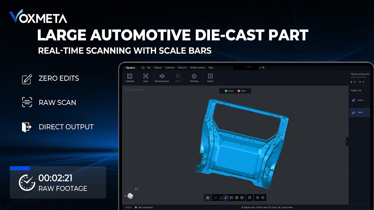
Automotive panels, castings, molds, machined housings, composite parts, and welded assemblies often have complex geometry, large surfaces, or widely distributed inspection points. These characteristics make full-surface scanning particularly valuable. To understand the difference between accuracy, resolution, and practical measurement capability, read the 3D scanner accuracy guide.
What Is the 3D Scanning Quality Inspection Process?
An effective process is straightforward: define the inspection objective before scanning, capture every important area, and then compare and store the results using a consistent method.
1. Define What Must Be Inspected
List the required dimensions, allowable tolerances, and priority areas. Determine whether the task is to inspect the overall profile, several mounting holes, or the alignment of a completed assembly. The clearer the objective, the more useful the scan and report will be.
2. Verify the Equipment and Working Conditions
Select the scanning method according to the part size, allowable tolerance, and surface condition. Calibrate the equipment before starting, then check result stability with an artifact of known dimensions or a verified reference part.
3. Capture Every Critical Area
Clean and secure the workpiece, then scan edges, holes, slots, and mating surfaces from multiple angles. For reflective surfaces, adjust the exposure, change the scanning angle, or apply a temporary matte treatment when appropriate. On large, smooth parts, careful 3D scanning marker placement can help the scanner maintain stable tracking.
4. Align the Scan to CAD Correctly
If a part is located in its real assembly by a specific plane and mounting holes, use those same features as references during the comparison. Automatic best-fit alignment is convenient, but it can spread a concentrated error across the entire part and make the original problem less obvious.
5. Create a Report Others Can Interpret
The report should identify the inspection locations, measured results, allowable limits, and pass/fail status. Record the CAD revision, alignment method, operator, and date. If a critical area was not captured, rescan it; do not use software-generated hole filling as measured evidence. For a broader methodology, see this 3D scanning workflow.
 Every stage, from defining the inspection objective to issuing the report, should support the final quality decision.
How Should You Read a CAD Deviation Color Map?
A CAD deviation color map displays the differences between the measured scan and the nominal CAD model. It can quickly reveal profile changes, high and low areas, mold wear, and assembly misalignment, but color alone cannot determine whether a part passes inspection.
Check three settings before interpreting a color map: how the scan was aligned to CAD, the deviation represented by each color, and whether the software applied excessive smoothing or surface repair. Changing any of these settings can make the same dataset appear different.
A mostly green surface generally means only that the measured surface lies within the middle range of the current color scale. It does not prove that every dimension meets the drawing requirements. Hole positions, mounting surfaces, and mating features still require individual checks. Software such as PolyWorks|Inspector can compare scan data with CAD and perform dimensional analysis, but its settings must match the drawing and inspection plan.

Can 3D Scanning Replace a Coordinate Measuring Machine?
In most cases, the two methods complement each other. 3D scanning is well suited to evaluating the complete visible surface, while a coordinate measuring machine is effective for precise checks of a limited number of specified dimensions. The best choice depends on part size, tolerance, accessibility, and the measurement environment.
A common approach is to use 3D scanning to evaluate the complete part and identify the deviation pattern, then verify critical dimensions with a CMM or another appropriate measurement tool. This provides both a broad view of the part and focused confirmation where it matters most.
How Do You Build a Repeatable 3D Inspection Workflow?
To help different operators obtain comparable results, standardize the conditions most likely to vary. For recurring parts, use the same positioning method, marker layout, scan coverage, software settings, and report template.
When scanning large workpieces, error may accumulate over a longer measurement range, so local accuracy alone is not enough. Read more about volumetric accuracy and error control for large objects.

Conclusion
The greatest value of 3D scanning is its ability to turn overall shape changes that are difficult to see into visual, measurable data. Define the inspection question first, capture every critical area, and use a consistent CAD comparison method so the results can support production decisions and process improvement.
If your team needs to inspect freeform surfaces, castings, molds, or large workpieces, review the VoxMeta H1 PRO specifications and application fit.


